Showing posts with label Wings. Show all posts

Tuesday, 9 April 2019

Navigation Lights

This blog covers the installation of the navigation lights and strobes.

Overview
The use of a camouflage paint scheme created some need to be seen in the real world, so the addition of lights was required, even for VFR operation. Also, after considering mounting methods, it was decided to glue the lens to the tip to avoid the risk of cracking. 

Installation
With the fibreglass wingtips covered in a previous blog, the final task was to install and connect the lights.


Opening for lens cut using Dremel cutting disc
Edge is approximately 12 mm wide
Aluminium 2024-T3 0.020"" covers used to match the profile 
of tip Short cover [no tab] slips through the tip while the other 
rests on the edge allowing glueing


Fixing cover -  Small dabs of Parfix urethane adhesive sealant
were applied to 
the edge to tack the sheet. The cover is held in
position with tape until cured. 
After curing a bead was applied around the perimeter on the inside edge.

Covers painted with gloss black. A pair of M3 rivet nuts were 
fitted to the removable cover to allow the screws to be removed from 
the inside of the tip 


The next task was to fit a LED Navigation / Strobe LED pack onto the fixed cover. It was decided to tap the brass inserts for mounting M4. To do this, the hole was enlarged to 3.4 mm to minimise drag while providing enough holding force.

The model selected was Aveo Powerburst Daylight Set in Red & Green.

These were connected to the wing loom using a four [4] pin Molex plug.

Note: Selecting lights again the builder would look for a model that allows rear fixing

The factory lens is a vacuum formed profile combining both lenses for both wings. An initial cut is provided, and this completed to separate the cover into two separate pieces. One is then placed onto the tip, and the first cutting edge marked using a Sharpie pen. This was cut using a set of sharp decal scissors, checked and sanded using 120 wet n dry to the marks. 

Marking initial cutting edge with Sharpie
Cutting edge - A denotes location relative to faring

Trimmed and sanded using 80 grit garnet paper
Edge marked allowing cutting edge to be located


Establishing a final sanding edge

The recess of the tip was filed to provide a constant depth and edge all around the tip. 

After a final check, a 5 mm bead of Parfix Acrylic Urethane Sealant/Adhesive was applied on the centre of the tip recess then smoothed to an even coating. The transparent cover was expanded at the far edge and inserted over the tip and aligned then several pieces of 40 mm masking tape were applied to hold it in position to cure.


Lens glued to faring
Covered with tape to allow the edge to be worked into the adhesive

Note: Here, the builder was a little too accurate, and part of the lens cover was found to lie on the curved edge of the tip requiring a quick trim with the scissors. Doing it again, the builder would ensure that the lens laid on only the flat area of the tip and then fill the recess with a sealant after fixing the lens in position.

With the masking tape removed the edge was prepared for the painting to cover the adhesive attachment with the cover masked to fully cover the attachment point plus 2-3 mm over. 

The paint used was Krylon Fusion Plastic paint, black spray can. This was applied in three [3] light coats and once dry all the tape and paper was removed.

Note: The painted area is confined to the area of attachment to avoid overheating the cover and to ensure as much support as possible on a hot day 

The backing sheet has an M3 rivet nut and screw installed to provide a handle to assist in the removal for cleaning.


Finished

The finished assembly was cleaned and polished with Mr Sheen Spray polish that gave a clean sparkle to the construction, smells nice too.

Comment
The biggest issue was the original decision to mount the light from the front, and this required the tapping the brass inserts M4 as the only possible access for mounting is from the rear.

Doing it again the plate for the attachment of the light would be 0.025'' 2024-T3 with a 0.020'' for the backing plate. The thicker sheet would be just stiffer to mount the backing plate; also, it would be folded in the opposite direction as this would provide improved access for cleaning and servicing.

Postscript
Tapped the factory bushes using an M4 tapered tap, installation used M4 x 12mm button head screws.

Wednesday, 20 February 2019

Wing Faring

This blog covers the fitting of the wing fairing.

Overview
After the disaster fitting the elevator faring the builder was determined not to repeat that event.

Installation
The first task was to mark out on the fuselage/wings all those locations were a hole cannot be drilled. Once done the factory fairing was fitted and the location of the first holes determined.


Tape to mark areas not to be used for a fixing

At this point, a Cleco was fitted and the next position determined, this process was repeated along the top side. Once completed, the lower flange was secured ensuring the fairing laid as naturally as possible on the wing. The final task was the nose and the underside of the rear faring from the flap back.


Note: Two additional screws could be added by reusing fixings on the main longerons fitted to the fuselage side. An M3 flush rivet nut was installed into a strip of 18 x 100 x 0.025" of 2024-T3 aluminium, then removing the rivets either side of the mounting hole to secure the aluminium strip with two [2] new pop rivets. The M3 screw is then inserted through the remaining hole to pick up the rivet nut.


At the rear, two [2] of the rivets for the last flap were secured the lower flange of the faring. To locate the hole a piece of cardboard of fixed to the top side of the skin and the hole located using a round jewellers file, finally, the outside edge was secured in position using a piece of gaffer tape for the next operation.


With the fairing reinstalled and secured with Clecos, the cardboard template is fitted to the top side of the faring using the gaffer tape as a hinge, next the holes locations are transferred to the faring top side and drilled.

The faring detached and the two rivet holes drilled to accept an M3 rivet nut. Finally, the fairing was secured using M3 x 12 S/S  Hex Socket Flanged Button Head Screws. A flanged head screw allows a reasonable clearance hole to installed in the faring.


Comment
Faring fitted as supplied and this was a surprise considering its size but maybe even this builder has learnt from some of his previous grievous errors.


Factory Tucano

Tuesday, 29 January 2019

Bits & Pieces No 9

This blog covers a number of small items overlooked in previous blogs on the wings

Main Spar Riveting
The spar laminates for the main spar have to be closed as tightly as possible for riveting, to do this screwed type Clecos are required.


Cleco Fasteners PLHN Series

The factory 3.2 mm holes are to be enlarged to 5/32 [4 mm] using a tapered hand reamer and battery drill. Starting with every hole fitted with a 3.2 mm Cleco from the tip, a Cleco was removed, then the hole reamed and a 5/32 Cleco fitted. 

Once enough were completed these were then replaced with the screwed Clecos. Finally these were remove one at a time and replaced with a 4 mm pop rivet.


Installing these required a little care as if they are not installed correctly they will pull through, this was found out early. 

Screwed Cleco was fitted by first extending the barb to its full length, inserting, next the outer sleeve was drawn back up by hand until the barb made firm contact with the spar face, finally, the nut was run down to a hand nip.

A ratchet ring spanner [shorty] was used to torque up the Cleco to create a firm grip.

Note: To do this the ratchet spanner was held close to the ratchet to prevent over-torquing

Wing Walks
The first point to note is it was not intended to flush rivet this area of the wing but when sitting in front of a warm heater with a pile of skins and a hand dimpler that master plan evaporated mentally and so that is that. 

On examination of the top hat supports, when dimpled, the small available edge distance provided evaporated so a new problem stuck up its ugly head. To fix this a 0.020'' packer was fabricated and new attachment method devised using more rivets. Once the fabrication was completed It was realized that a centre packer would be required, one was fabricated from the same aluminium sheet with an additional row of rivets added to secure it to the top skin.

Nose wing walk and attachments

Faced with the same problem at the other side a large enough piece of aluminium was sourced to make a once piece packer/attachment. 

Note: The edge distanced here were tight than theoretical but even if the holes are correct centerline the aluminium stiffeners plates take 3.5 mm of the available distance, doing it again this builder would examine placing these on the outside of the ribs to regain 3 mm on each side - it would help.

Fuel Tank Installation
The last two skins should have not been riveted to allow installation of the fuel cap adaptor seen below after the tank is installed. This procedure is noted in the new kit notes and it was all part of the builder's mental plan but in the excitement of riveting was lost.


The installation of the fuel tank neck seen in the upper right-hand corner created hours of fun to install along with the prerequisite mess, cuts and bad language that such tasks create. 

Note:  A word or warning to place notes on the panels when thinking of these things would have avoided this issue.


Comments
More of the same

Monday, 21 January 2019

Bits & Pieces No 8

This blog covers a number of small items overlooked in previous blogs on the wings / flaps

Aileron's
Both ailerons were checked before closure and meet the minimum engagement but at this point, it was noted that access to the rod end mounted to the bell-crank would be difficult to access to replace the rod end bearing.

Note: The minimum thread engagement is 1.5 times the major thread diameter - Aurora Bearing Company. 

The factory advised that an additional access hatch would not be required but the words of Kel Gore [Great LAME, now gone] echoed in my head "Cut one now because if I have to, it might not be so pretty". With those wise words, a cover was installed onto the inside face of the skin, secured with 6 x M3 rivet nuts with another cover was fitted externally using M3 x 12 pan head S/S screws. 

If needed, all that needs to be done is drill a 90 mm hole at the centre of this assembly.

Note: The bellcrank has been redesigned and relocated on the new models, this is no longer an issue.

Flaps
The attach brackets were fitted using 4 Dia x 13 multi-grip rivets using the pre-drilled holes on the outside rib, all four [4] holes were reamed to clean them for riveting. 

Four [4] rivets were driven into their mounting holes using a small socket and then pulled using the small rivet gun.


Countersunk Riveting
All holes were dimpled using a simple hand tool, while not ideal it proved to be cost effective. 

To achieve the best possible finish when fitting countersunk rivets, it has to be pressed into the dimple using the rivet gun with the centre-line of the Pop Riveter as perpendicular to the surface as possible before pulling the rivet. 


Stringers
The top and bottom stringers were secured at both ends using a T shaped clip to place the stringers face flush with the top side of the rib. The clips place the stringer flush with the top side of the skin, in particular, were a rib and two skin meet creating a 0.05'' thick attachment point.

The mounting faces were coated with black polyurethane adhesive/sealant at assembly to help ensure a tight assembly when riveted. 


Checking fit before fitting

To prepare to fix the stringers a centerline for the stringers was marked along the outside of the skins, next the rivet centres were marked starting by marking 20 mm from the centre line of each rivet line. At each bay, the distance between each mark was measured, divided by 40 and corrected to a whole number, finally, the centres marked. In most cases on this aircraft, this worked out to be between 38 and 40 mm across all 5 bays.

This operation is required to be undertaken at the top and bottom.

Note: A cheap compass with a fine line felt pen was used to mark the centres.

Next, all holes were drilled and a centre line added along the full length of the stringer. With the stringer installed is was manoeuvred over one of the holes at each end by sighting the line through one of the drilled holes, a hole was drilled and clecoed, this operation was then repeated at the opposite end and finally at the centres the centre of the line.

Once happy with the locations of these 4 holes all holes were matched through the stringer then the skin/stringer was dimpled and finally the skin/stringer prepared for final installation
Note: This operation is criticial, there can be no errors
Fuel Lines
With all the fuel lines installed they were all tested with air pressure to check for leaks. While most of the key points have access hatches it would be better to rectify issues before the skins were fixed. The pressure regulator on the compressor was lowered to about 10 psi and all open ends were sealed with plugs and the springs removed from the return check valve allowing a full system check. Each joint was checked by spraying with detergent/water around each joint while checking for any bubbles, all joints passed.

Pressure testing lines

What's wrong in this picture?

After completing the 3.2 mm riveting on the starboard wing and then working on the port wing a large OMG was noted. 

The last two skins should have remained un-rivetted at the topside to allow installation of the fuel cap adaptor. This builder had started blindly building an aircraft not assembling an aircraft. This procedure is noted in the new kit notes and the builder was fully aware of this, in fact, it was all part of the mental plan. 

To fix the issue an area of skin was de-riveted and some careful aerobatics performed to install the adaptor and connect all the aluminium pipes for the static line. This created many hours of fun along with the prerequisite mess, blood and incantations. 

Note: BEWARE and think when you have a rivet gun is in your hand.

Comment
There will be more little bits to tidy up

Monday, 3 December 2018

Wing Tips Installation

This blog cover the installation of the wing tips

Overview
It was decided to try and obtain a better match between the faring and the wing tip by mounting attachment strips to the side of the rib instead of using the 0.5mm [0.020"] aluminium strips fitted to the elevator stab.

To do this four [4] strips were laser cut in 1.0 mm marine grade aluminum by Laser Wizard using a DXF file provided by the builder.

Installation
The profiles were first folded into a right angle to allow installation, next they were offered up to the end rib and trimmed to fit and then alodined.

Starting at the front a 1.0 mm angle was used as a spacer between the top side of the skin and angle. Supporting the spacer while using a finger to determine the correct location for the angle a hole was drilled and cleco fitted. This operation was repeated for the length of the angle.

When the aft rib was reached the limitation of the arrangement was encountered as this builder managed to hit a number of factory holes or just no metal. To compensate for this a sheet cover was fabricated and riveted to the face of the rib. 

While not perfect, it is a solution.


Angle strips ready for installation

One the starboard a couple of the holes were slotted using a 3 mm OD file to adjust the position while the port side went smoother - practice is of some advantage here.

Next the factory tip was offered up to check the fit and once satisfied the location for the fixings was marked from the rivet line using the same techniques used for the rudder / elevator stab.

With the top side fixed using 3/32'' clecos, time to look at the underside. Here there was a distinct gap due to the rib and skin fit. There was a blog on the "Cat in the Hat" , this was for the efforts to align the faring at the top of the rudder fin, here the builder tried to sand the tip into alignment and ended up with that hat from that famous cat.

It was decided this time to add material so the tip was remove and a strip of fiberglass added. This was manufactured using two layers of 8 oz cloth and epoxy. 

It was placed between two boards covered with packing tape then brick added to the top board. this produces a ultra thin strip of fiberglass tape. This was cut into a strip 25 mm wide and fixed to the inside face of the tip using 5 mm epoxy.


The edge on the tip was chamfered along the fiberglass tape using a Dremel and sanding drum, then Plasti-Bond was applied and allowed to harden. 

The tip was offered up again and the profile obtained with multiple sands / refit / sand - get the picture it's called time..!


The dark edge is the filler and the text - the instructions of what to do
when removed many times

Once satisfied with the profile the mounting holes were drilled as per the top side.

All holes were drilled 3/16'' and fitted with M3 rivet nuts pressed into the hole to engage the spline. All holes in the fiberglass were enlarged to 4 mm od using a tapered grinding stone fitted to the Dremel motor tool. 

Finally the tip was refitted and secured with M3 x 12 S/S flanged button head screws.

Next it was noted that the aileron fouled the tip with the solution begin to notch the edge to align with the aileron edge.


Foul with aileron

Comments
It is critical that the skins are in a line not staggered, the lower skin on the underside had to be removed and trimmed to rectify this issue. 

The angles worked well BUT if doing again it would be developed over a accurate drawing of the end ribs to ensure ease of assembly and accurate layout.

Overall not hard once you get a good assembly procedure. 


Always another job

Aileron Installation

This blog covers the final installation details for the ailerons.

Overview
The ailerons had been assembled previously leaving the final details to the final installation.

Installation
Note two [2] washers

With these issues sorted and a lot of lost time, the only practical way to assemble the brackets then connect the aileron was to fit the brackets to the aircraft first.

Both bearing mount require an AN4 aluminium washer to be inserted on both sides between the face of the bracket to avoid fouling but on final installation the inboard mount required two [2] on one side to clear the rivets. 

The next task was to fit the rod end bearing, to locate the bearing, a pair of 3 mm spacers were machined from 4130 tube to fix the rod end location. Additionally two [2] seal were added to protect the working face from the environment.


Stainless steel and aluminium have some known corrosion issues so all mounting face were painted in SLS Etch primer before installation. 


Primer on mounting faces

With both hinges fitted the aerlion was mounted with AN3 bolts / washers using the captive nut fitted to the spar. This task is not easy and dose require the use of a set of fine bent long nose pliers, assorted tools and floor gymnastics on the trolley.


Leveling Aileron

The next task was to adjust the shaft connection between the aileron / bell crank located in the wing. This required locking the aileron into a their neutral position, this was achieved  using a piece of aluminium angle and clamps.

Next the push pull tube was placed in it neutral using the center rocker arm, this was placed perpendicular to the spar face. The rod end at the bell crank was unbolted and adjusted in conjunction with the one attached to the aileron bracket, when correct the lock nuts were tightened and wax marked.

Note: It is critical this be undertaken while access is available from the underside of the wing  as there is no access to the rod end bearing on the bellcrank with the skin on.


Bell Crank

A particular issue that appeared was that the end rib was not square and this required a small amount of Plasti-Bond to be applied and sanded to achieve a flat face, once sanded the mass balance was reinstalled using three [3] M5 x 16 mm Titanium Button head screws.

Note: Screws were used over rivets at installation as it was suspected that something was not 100%.

This was noted when the tip was installed and will be covered in that blog at a later date.


Mass Balance and filler [upper right hand corner}

Comment
Generally straightforward once the best way to achieve assembly was understood.

Monday, 12 November 2018

Wings Assembly

This blog covers final assembly and associated details for the wings - both wings share common details but the photos are a mix from both.

Overview
Task to assemble all the hardware into the wings for skinning.

Installation
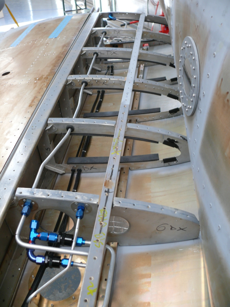
The first task was to install all the piping for the return lines and for the pickups for the external [future] tanks. A trail fit of a tank previously showed a clash with the fuel sender required a U to route around it plus a few Aeroflow fittings. At this time the pitot tube and wiring were loomed and installed on the underside of the ribs. The wires cover strobes and power /signal for the under wings tanks on both sides.

Note: All fittings are all full flow not 90 degree as per aircraft AN fittings


With the pipes installed the tank was fitted to allow connection and fitting of  the components onto the tank.


Note: Last rib is only clecoed allowing all the tank fittings to be installed except the fuel cap which is last.


External tank fuel and electrical connections
Access hatch is for service and connection when commissioned 

Fuel return and delivery lines from external tanks port side
Fuel delivery line from external tanks. Loom is for strobes and external tanks pump / low fuel indicator


These photos are from the starboard side and are a duplicate of the arrangement on the port side.

The skins were installed and clecoed from the underside to provide access and to locate the ribs allowing the tubes and electrical to be cut and installed.

The leading edges of these wings are dimpled and without doubt this has quadrupled the work to install the skins. 

In particular when installing the stringers the skins were removed and reinstalled to many times to count providing access or alignment for the top or bottom stringer and then at either end to install the T clips shown below.

The connection to the check valves at the end of the tank have been changed from rubber to aluminium as I had to purchase a new roll of aluminium and it was there and lighter.

Work on the piping was much easier as it was really a copy of the port side and visa versa for the working and associated clips.

It was decided to fix the stringers to the ribs using a T clip made from 2024-T3 aluminium to place the stringer flush with the skin from rib 7 to 4 and then fit a 0.025'' packer from rib 4 to 1 

In the photograph below there there is 0.05'' of metal [rib and skin] and the Tee will place the face of the stringer flush with the top side of the outer skin when the next skin is placed on the wing.


The Tee is at odd angles because the stringer runs at an angle to the spar because of the wings taper with 0.040'' chosen for stiffness and ability to be countersunk 
All holes are 120 degrees to suit pop rivets

Comment
The tanks will be covered in a separate blog to keep it tidy but they are integral to this process and they were removed and reinstalled too many times for fitting.

There are a number of small items to add and these will all be covered in a final wrap up blog on the wings. 

The final word is below - port next but running out of clecos


More on the underside