Tuesday 20 October 2015

Elevator Alignment - Part 4

When Franco meet me at the hanger about the Tucano he commented that make sure that I aligned the elevators. The impression was that all the holes are drilled, "what could I align" as each elevator when assembled was quite ridged joined by a torque tube. 

Elevator assembly was simply a matter of bolting and riveting the torque tube using the pre-drilled rivet holes and nut plated installed in the elevator's.  When the alignment of the hinges was checked a distinct misalignment was noted but after packing and packing it was concluded that this approach was leading in the wrong direction, time to stop and think!

The Jig
What was needed was a jig or a fixed reference and that lead to the stab which is both rigid, straight and the elevator surfaces has to bolt to it.
Packer port side

A string line was run through the center of the four [4] hinge mounting holes and it was concluded that a 0.030'' packer was required behind the port outboard hinge to bring all onto the same center. 

This was fabricated and riveted on its center to the spar using two [2] 5/32'' pop rivets and when rechecked the string was on all the hinges centers. It was now ready to be used as the jig to align the elevators using the aluminium D nose to lock the elevators into correct alignment to the stab and fuselage.

Port Side check
Starboard Side check


Elevator Alignment 
With the fuselage level with the tail plane the assembled elevator was fitted onto the stab. The next task is to align the trailing edge of the elevator to the stab, this was achieved using another water level and a piece of lumber to hold the tubes into position. 

The elevator was twisted into alignment by placing an aluminium angle prop under the inboard edge while resting on a clamp with the extra 3 x 2 there as dead weight.
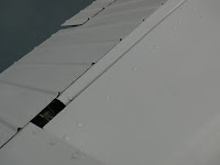
Starboard Elevator - Aligning & fitting D nose

Cessna D Nose

With the elevator level the D Nose was taped into it's correct location using duct tape then checked and match drilled at one end then the other, clecoed and rechecked. 

Note: The lower edges of both D Noses had been pre-drilled before installation with the folded edge a few mm from the face of the spar. Positioning the skin equally from the face of the face of the spar located the D Nose in the correct location providing the clearance for correct operation and a neat appearance when assembled. 


Comment: Keep the skins is a safe place and do not separate from factory packing until needed. Handle as little as possible as this aluminium is very soft and will damage easily.

The supplied skin has a large excess of material - do not trim until the mounting holes have been fully drilled.

My decision to place the D nose under the skin is based on the need to control the shape to match drill, its the same arrangement used by Cessna with the profile begin the same as the Tucano's. 

Finally a series holes were drilled, clecoed then the balance will be matched drilled on the bench for final riveting.


Port Elevator - Aligning & fitting D Nose

The procedure was repeated on the starboard elevator using the same reference point on the outboard edge. The inboard edge was ignored as it was leveled with the port side as the horn is a rigid connector of the two inboard edges.

The final task will be completed at the next secession but will require removal, de-burring and removal swaf and other tasks before re-assembly and riveting.

Monday 19 October 2015

Air Show Aftermath

This blog is to be a honest account of the history of this exercise - this is the bad but with a happy ending - read on.

Factory repair scheme

On return from AUSFly 2015 the fuselage was unloaded from the return trip with all seemingly OK until the fabric strap used to hold the fuselage at the rear was removed and the damage to rib 9 and the port skin was uncovered. Without the boring detail the rear was located at the rear of the trailer for the return trip and it can be concluded at the additional acceleration collapsed the rear support allowing the rib to ride on a hold down strip and the rest is history.


Happy Days at AusFly

The factory was contacted and the repair scheme above was received within 48 hours and the parts were manufactured, alodined and dispatched with the supercharger upgrade kit.

While this was inconvenient and not a task I would willing seek out, it was one of the reasons I chose to build a conventional aluminium factory kit.

It can be repaired in the field with basic tools and should be part of any builder selection criteria. While it may grant bragging rights to have a kit built using the latest honeycomb graphite composite remember that you have to maintain it - a point to consider

The Repair
Rib No 9 was a total loss and Rib 8 had a couple of small creases and it was decided to remove it on spec. Once removed the longitudinal channel was straightened as much as possible and the new channel slipped over it and match drilled and clecoed.

Next the damaged rib was cut out using aviation snips and trimmed back to the underside of the longeron leaving the existing attachment brackets in-tack. The scrap for the No 8 rib was used as a drilling jig for the lower attachment but the damage to the No 9 rib precluded this approach.

The new rib was trial fitted and aligned to the channel doubler. When satisfied the first mounting hole for the No 9 rib was drilled - re fitted and all other holes match drilled. This was repeated for the other side then the flange's at the center tab. 

Next the No 8 rib was installed using the pre-drilled mounting holes as the starting point then all other holes were match drilled.

The channel was now reinforced with a length of aluminum angle and the tabs to attach the rib to the channel were pre-drilled to mount to the rib's, then the assembly match drilled. A single counter sunk 3 mm rivet was installed to secure the assembly. 

This operation was repeated at the next rib.

The sides were match drilled into the rib flange on each rib and cleoced. All bulkheads were fully riveted using 3 mm x 8 pop rivets at each attachment point including two rivets into the flanges.

The next task was to fit the undamaged skin on the starboard side to check alignment. This was slipped  under the side skin and wrapped around using the two remaining drilled rivets to meet the lower channel.

A number of the other ribs had holes drilled using the skin to assist in this task. The lower flange is highly mobile and this resulted in the rivets location 2 - 4 mm from the flange of the rib and I suspect that they were not exactly in the correct alignment but in the case of the No 9 rib it had little give at this point so the alignment had been set at assembly

Repaired No 9 Rib

 New Skin
The factory supplied two new skin's and one was placed on a flat table laying on 6 mm aluminium foil insulation that proved perfect for this task by allowing the drill to clear the skin and the cleco to bite at the hole created in the foam insulation effectively locking the job as the cleco's were added.

The damaged skin was cut to allow it to lay flat with weight applied and the holes traced around the sheet. 

The holes for the connection at the channel will be matched drilled at installation

Next working week we close the rear to allow the tail to be fitted. 

To at least make me feel better when the liquid level was checked on the tail plane, it was perfectly level with the fuselage - all well that ends well.


Back were it all started

Tuesday 13 October 2015

Canopy Frame - Part 3

The canopy now freely hinged but the port side sill requires pins to fix its final location when closed. Factory supplied aluminium 12 mm pins are installed for this purpose and require the frame to be positioned to achieve it final alignment. 

Pin Installation
The canopy was now taped using the reference line at the port side as mention previously in Part 1. At this point it was decided to add a 1 mm packer under the rear spreader to allow the overlap to close smoothly and allow the location pin to be installed.


Positioning Pin
The underside of the canopy has three [3] holes drilled to position the locating pins. It was decided to enlarge the hole using a step drill to 9/16'' to locate the pin on there taper with the canopy closed and locked in it final position requiring more tape.

When ready the tape on which the pin was resting was marked at 3 places and the canopy opened. With the pin located on the center of the circle the canopy is closed.


Locating pin center
The pin was checked and when satisfied the center was located by using a square from the side of the fuselage to mark the outer edges of the circle the a ruler use to locate the center and this was repeated on the other axis using the circle edge.  

The center was marked with a automatic center punch then enlarged in two steps to suit the M4 rivet nuts supplied. As they cannot be expanded fully due to the thickness of the metal, Loctite 308 Black Max Super Glue was applied liberally to both faces before expansion.

A M4 x 50 screw was installed and cut to 30 mm long for installation. Next the hole for this pin was enlarged to 12 mm OD and finally the pin was installed. 

The canopy was swung and the installation verified. 

This operation was repeated at the front then the center using the same procedure.

Pin Adjustment
On this installation the canopy swings slightly forward off it's correct location, it was decided to pack the pins into three [3] steps. The front one is the highest with the second and third on 3 mm steps.

The canopy is thrown over and rests on the pilots [front] pin. A slight reward pressure and the pins all cascade into location. 

Canopy Frame
The final task was to sand to lower edge of the canopy frame into alignment. With the canopy closed and taped shut a 2 mm strip of metal was used to mark points along the canopy edge using the top side of the longeron as the reference.


Scribing sanding line
The Port edge was flipped over and a steel straight edge was used to create a line of best fit, then with a dab of caution a line was scribed using the Ofla knife into the canopy coating.

A single cut bastard file was now used to file to the line and the whole lot finished with 180 grit aluminium open cut paper on a sanding stick. 

The canopy was closed and a series of 2 mm packer placed under the edge and final adjustments noted and sanded as required.

This operation was repeated on the hinge side but required the canopy to be removed to undertake the work.


It works.........!

Comment
It is hopped that once the canopy proper is installed a lot of the flexibility should disappear , time will tell. Once the canopy is in place the builder will re-visit the engagement with the front pin but is in no doubt that it will be nearly 100% when finished.

The next job is fitting the perspex molding and that will require some solid drinking time to approach ...!

Was this a good way to approach the exercise - hell I don't know but the builder got there and there were no book of rules to say I am wrong - yet.


Monday 12 October 2015

Canopy Frame - Part 2

With the starboard side fixed the port side was still a moving feast so this was the next major task.

The factory had advised me that it would be better to fit the spreader shown on the plans at the center not the rear but as the canopy was cycled with the single spreader it was clear that on this aircraft both would be required so it was decided to add a additional one at the center.

Center Spreader
Attachment
The spreader was fabricated from a piece of 40 x 12 x 1.6 mm 2020 aluminium extrusion that was on hand. 

This was cut to size 8 mm undersized and then a series of 20 mm holes pitched at 38 mm centers were drilled along it's center.

A pair of attachment angles was next fabricated from 0.030 2024-T3 aluminium and then all items were primed for assembly.

The frame was taped into position and aligned with the reference mark and this is critical, if not done the spreaders will be in the wrong position.


Center spreader installed.
Gray marks are epoxy metal filler from a incorrect installation

The 60 mm position is a minimum distance and any closer the bar will foul on the roll bar when flipped over.

Rear Spreader
The attachment angles were re-fabricated to allow the spreader to align with the face of the baggage compartment after begin relocated from the center. The actual angles are a compound of various facets so a 40 wide angle was fabricated from 0.040'' 2024-T3 aluminium and clamped into the frame as shown.


Setup
The spreader was leveled with a digital  level using the top side of the wheel well as a zero reference. The top side of the spreader was then marked and the angle removed.

With the angle on the bench a tab was cut to fit to the inside face of the spreader , then the assembly was reinstalled as shown and the spreader centered with the two mounting holes transferred to the tab.

This was removed again trimmed and pop riveted. Finally the opposite side was now trimmed and the mounting holes drilled.


Attachment tab - both side
Installation
Alignment of the mounting holes was the next issue as with a little extra pressure it would move with no control. 


Reference lines
A series of reference lines were added to the side of the canopy frame using the baggage compartment as the datum. 

The spreader was installed and clamped into it final position using these line's for alignment. 

Once satisfied one hole was drilled, clecoed, repeated on the opposite side. A final check, tweak and the other pair were drilled, then all pop were riveted using 3.2 x 8 mm rivets supplied with the kit.


Finished Spreaders


Canopy Frame - Part 1

The canopy frame is hinged on the starboard side as per the prototype Tucano using two factory supplied hinge sets and a monster one piece frame measuring 2.3 x 0.6 meters.

The initial trial fit showed that it lined up with the cockpit profile leaving only one larger question - Where to start?


Overlap
After careful consideration of the plans and aircraft it was decided to fit the hinges as a starting point. 

The lower hinge's were riveted to the longeron previously allowing the frame to be positioned onto the air-frame and taped into it final position. As the frame is fairly flexible two main points used to align and position the canopy frame. The V at the junction of the top longeron's and the overlap  around the baggage compartment.


Canopy frame alignment

Note: The use of the alignment point's on both sides is critical as the canopy frame has to be removed and taped back many time's in the process and this allowed the frame to be re-positioned correctly each time.

With the canopy frame in it assigned position the position on the cutout for the hinge was marked to accept the full hinge plus a margin for adjustment. These were cut out and dressed back to the top side of the canopy frame using a single cut medium bastard file.


Cutout for hinge

The hinges were trial fitted to the frame and two differences were noted - the front hinge was at 90 degrees with the rear at least 100 degrees. with this in mind the hinges were pinned together and the frame fitted and taped into position. This indicated that packers were required to allowing the hinge flange to be fixed to the frame side while maintaining alignment. 

Two spacers were manufactured with the front begin 3 mm thick and the rear 6 mm thick. Next the packers were fitted and clamped and a test swing undertaken which indicated that all appeared to work. 

It was decided to fix the front hinge to the side with the base hard on the underside of the frame - remember the angle this will reveal itself later.


First correction
With the frame in it final position it was noted that to fit the rear hinge flush with the base the frame the flange would have to be corrected. This was undertaken with a lot of heat and  clamps, 3 mm stainless is tough stuff.


Correcting the correction

The corrected angle was fitted with the frame removed and this was were the rub revealed  itself - the frame base is not at 90 degrees more like 100 and the fit was worse, back to the bench to correct the flange back to where it was. 


The gap

Front Hinge Installation
A check pf the front hinge also revealed a massive gap as the original opening was only just to clear the top side of the hinge and once fully dressed to match the rear was the gap revealed.

The solution chosen was to grind an aluminium tapered wedge 5 mm thick x 22 long and fit it with a film of epoxy metal at the mating face and rivet with 4 mm x 12 pop's.


Wedge


Note: Modifying the angle would have lowered the canopy base and the hinge pin just fitted and it was not considered an option.


Front Hinge - Assembled

Rear Hinge Installation
With the angle set and the canopy frame reinstalled and aligned the hinge was fitted to the frame. With the hinge in its correct position the pivot point did not align and a base packer is not a option so again the hinge was removed, heated and bent. This required a number of operations but it was finally positioned to the builder satisfaction then assembled.

Note: The pin was installed at all times to maintain alignment and the final adjustments were to ensure that the pin can be inserted with a minimum of force.


Rear Hinge Assembled
Note offset to align pivot point