Tuesday 18 December 2018

Throttle Body Injection

This blog covers the design criteria used to select the Rotec Throttle Body Injector for installation onto the Rotax 912 used on this aircraft.

Overview
The Bing Carbs along with the inlet manifold used on the Rotax 912 are a practical compromise but far from ideal, there are many aftermarket EFI systems but all share a flaw - single channel.

The Rotax 915 features dual-channel electrics/electronics or in plain language a redundant system with two means of fuel/ignition, while ideal, its complex and adds weight with the 915 tips the scales at 84 kg plus extras. 

Aftermarket EFI systems have no reported history of failure, most pilots will never in their flying careers use any of the dual redundancy incorporated into a typical certified aircraft engine but this only means there is a very small statistical chance of a failure but when it is required its 100% significant to that pilot at that point in space and time.

Regardless of which EFI is used, they share one common requirement, that's for the Rotax's regulator to keep working and it's the one item incorporated into a Rotax engine that is considered a weak link. The electronics operating an EFI system use's 5 - 8 amps, leaving only 10 amps available from the Rotax alternator to maintain the battery and panel electric's so a larger alternator may be required, more weight/cost but at least there is a backup available. 

The need to have an operating electrical system also means you have to have a larger [heaver] battery and the 1 kg battery that is installed will not provide the necessary flight endurance to an alternative airfield.

Note: In the event of total electrical failure there is a high drain on any battery and at 11V a battery is considered dead flat. 


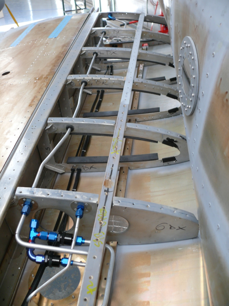
Dog Aviation review on the RV12 and the Standard Ducati Regulator


 Photos are taken from Dog Aviation images investigating a series of 
RV12 regulator failures


SDS EFI  "Aircraft engines are essentially constant rpm load devices, spending the majority of their lives at fixed power settings for long periods of time. Once a power setting is established, the injector on-time and ignition timing remain the same until power is changed. 

For this reason, we feel that 3D mapping offers no useful benefits, it merely complicates understanding and operating the system for most people"

An alternative was not available until Joe Newman from Marwen discussed with Pual from Rotec that the TBI should work with a supercharger as the new Mk2 version incorporated an internal pressure reference, at this point both agreed that they could not see a reason why it could now not operate under positive pressure, it was unproven but now worth a look, Joe had with one in his bag on his return to Rylstone. 


Note: The Mk 2 Rotec TBI now an upgraded version of the proven Ellison TBI

Installation of the single Rotec TBI onto the Tucano engine was the only option as the dual TBI setup would not fit.


Service kit - it's that simple
A suitable TBI manifold would require flat runner exits, equal length runners and large volume. 

At this time the FAA approved plastic Ultem 9085 was selected to manufacture all the necessary parts using FDM printing.  A lot of time was put into to optimising the design with FEA to obtain a feel for how the plastic would perform. FEA can create an unreliable results with plastics so the design parameters used were at 140 degrees C to analyse a single state, while not a 100% accurate it's better than a guess. 

Rotax 914 engine cannot be operated at greater than 88 degrees C and therefore 140 degrees C was selected as the structural design point with 100 C as a maximum operating temperature. A Rotax cam has little overlap so pressure waves from the opening of the inlet valve have been ignored as a design load.


Ultem 9085 plastic was chosen for its superior Izod number and heat deflection temperature [HDT] and strength at elevated temperature.


Material Specification

A 3D model estimated an assembled weight of 1.8 kg for the throttle, body/manifold/primer which is 1.2 kg lighter than the Rotax assembly it would replace.


Proposed Manifold/TBI/Inter-cooler
3.5 kg as shown [design weight 4 kg]


Elevation
Plan

Note: A Rotax engine MUST NOT exceed 88 degrees C, so a temperature probe is to be installed at the inter-cooler outlet allowing the temperature to be monitored.

The biggest issue at this time is this may not work, why, the Mk 1 Rotec will not operate under positive pressure but the Mk2 may because of a major design change Joe from Marwen noted at Oshkosh.  

To prove the design a 3D printer will be purchased early next year to manufacture a working prototype and it up to both of us to prove it works as a system. If it does work it will be 2/3 the price of an injection system and lighter - worth the look.

If it does not work back to the drawing board and on go the Bings.


Meshing basic manifold


Stress at peak [red] about 4 Mpa with 20 Mpa on Z axis allowable at 140C
Simple manifold used as this is within the limits of the package available

The model has a 3 mm thick wall, a wall thickness of 2.5 would be acceptable 

Comment

What if, what if?

Thursday 13 December 2018

Engine Supercharger Upgrade

This blog covers preparing the engine for the supercharger and some of Marwen's work and discoveries about Rotax 912ULS cylinder heads

Overview
The selected engine had a total of 140 hours when it was removed from a wrecked Foxbat which as a result of the accident suffered a prop strike. The engine was inspected and signed back into service by an approved Rotax agent at the time of purchase but it was decided to verify.

To achieve this, the engine was stripped, cleaned, painted black and fitted with a full set of O rings etc to bring the engine back to nearly zero time. One issue noted was that this engine had seen a lot of service running LL Avgas and this required about two [2] hours of cleaning by Joe from Marwen.


Checking engine mechanicals

Engine assembly

All the gears and crank checked out to specification so Joe [ex-race bike mechanic] decided to check the final compression ratio as he always had done when racing. While a relatively simple operation it revealed a static compression ratio of 9.6: 1 which would create an effective compression ratio close to 13.6: 1 [worst case].  


Joe was concerned and contacted me, we looked at options like knock sensors but the real issue was the compression ratio. 

The starting ratio should be 8.5: 1 - where was the error?

Note: Worst case was defined as the smallest combustion chamber - they varied by about 3 cc and due to the small swept volume this had a large effect.

Joe checked his figures again & again and they came out the same, there was an error somewhere. Joe next calculated back to the factory compression ratio, it was 11.1: 1 with the accepted ratio for a 912ULS generally understood to be 10.5:1.  This was answered when Rotax released it's current heavy overhaul manual which clearly states the compression ratio is now 11.1: 1 for these engines.


Extract Rotax Heavy Overhaul manual - page 12

Modifications 
Marwen Spacer 1.5
We have decided to decompress the motor further with the original 1.2 mm spacer rings replaced with 1.5 mm rings and the heads CC to match the largest measured volume. 

This realized a compression ratio of 9:1 and gave a effective compression ratio of 12.7:1 with a 6 psi of boost.

The next issue was that the original 1.2 mm spacers left the hydraulic lifter with only had 0.8 mm of travel and now with a 1.5 mm spacer it would be 0.5 mm [0.020''], we were edging close to mechanical lock up. 

This issue is to be addressed by manufacturing custom lifters placing the hydraulic lifters back onto their mid position [+/- 2 mm]. 

CC combustion chambers as part
of setting the final compression ratio
Comment: 
The comment below was taken from the Pro Power site but generally, any search will yield the same comments at many sites - edited here for clarity with this case.

"For 9.5:1 EFI/TPI applications running without an intercooler, boost levels above 5 psi will require the use of ignition/timing retard on pump gas, and will produce horsepower gains of 35-45%.  Of course, lower compression motors will be able to run more boost, and higher compression motors should run less boost, everything else being equal. 

For carburetor motors, the rules are slightly different. 

Carburetors deliver the vast majority of fuel in a liquid state, and as this raw fuel atomizes from liquid to gas, a chemical state change actually occurs. Due to this endothermic reaction, which draws heat and cools the incoming air, a carburetor motor can safely handle more boost than a comparable EFI/TPI motor. For carburetor engines with compression ratios of 9:1 or less and boost levels in the 8-14 psi range, pump gasoline works very well. "


Joe cool and sidekick
Does the current arrangement work, well yes but with the measured increased compression of 0.6 points an intercooler should be considered. Also as we intend to improve fuel delivery so any protection created by over fueling may not be there.

This one is open to comment .!

For this aircraft, we decided to err on the side of less power to help stave off any chance of detonation on those very hot Australian summer days.


Methanol injection would be an option, Joe Cool loved racing on methanol.


Monday 3 December 2018

Wing Tips Installation

This blog cover the installation of the wing tips

Overview
It was decided to try and obtain a better match between the faring and the wing tip by mounting attachment strips to the side of the rib instead of using the 0.5mm [0.020"] aluminium strips fitted to the elevator stab.

To do this four [4] strips were laser cut in 1.0 mm marine grade aluminum by Laser Wizard using a DXF file provided by the builder.

Installation
The profiles were first folded into a right angle to allow installation, next they were offered up to the end rib and trimmed to fit and then alodined.

Starting at the front a 1.0 mm angle was used as a spacer between the top side of the skin and angle. Supporting the spacer while using a finger to determine the correct location for the angle a hole was drilled and cleco fitted. This operation was repeated for the length of the angle.

When the aft rib was reached the limitation of the arrangement was encountered as this builder managed to hit a number of factory holes or just no metal. To compensate for this a sheet cover was fabricated and riveted to the face of the rib. 

While not perfect, it is a solution.


Angle strips ready for installation

One the starboard a couple of the holes were slotted using a 3 mm OD file to adjust the position while the port side went smoother - practice is of some advantage here.

Next the factory tip was offered up to check the fit and once satisfied the location for the fixings was marked from the rivet line using the same techniques used for the rudder / elevator stab.

With the top side fixed using 3/32'' clecos, time to look at the underside. Here there was a distinct gap due to the rib and skin fit. There was a blog on the "Cat in the Hat" , this was for the efforts to align the faring at the top of the rudder fin, here the builder tried to sand the tip into alignment and ended up with that hat from that famous cat.

It was decided this time to add material so the tip was remove and a strip of fiberglass added. This was manufactured using two layers of 8 oz cloth and epoxy. 

It was placed between two boards covered with packing tape then brick added to the top board. this produces a ultra thin strip of fiberglass tape. This was cut into a strip 25 mm wide and fixed to the inside face of the tip using 5 mm epoxy.


The edge on the tip was chamfered along the fiberglass tape using a Dremel and sanding drum, then Plasti-Bond was applied and allowed to harden. 

The tip was offered up again and the profile obtained with multiple sands / refit / sand - get the picture it's called time..!


The dark edge is the filler and the text - the instructions of what to do
when removed many times

Once satisfied with the profile the mounting holes were drilled as per the top side.

All holes were drilled 3/16'' and fitted with M3 rivet nuts pressed into the hole to engage the spline. All holes in the fiberglass were enlarged to 4 mm od using a tapered grinding stone fitted to the Dremel motor tool. 

Finally the tip was refitted and secured with M3 x 12 S/S flanged button head screws.

Next it was noted that the aileron fouled the tip with the solution begin to notch the edge to align with the aileron edge.


Foul with aileron

Comments
It is critical that the skins are in a line not staggered, the lower skin on the underside had to be removed and trimmed to rectify this issue. 

The angles worked well BUT if doing again it would be developed over a accurate drawing of the end ribs to ensure ease of assembly and accurate layout.

Overall not hard once you get a good assembly procedure. 


Always another job

Aileron Installation

This blog covers the final installation details for the ailerons.

Overview
The ailerons had been assembled previously leaving the final details to the final installation.

Installation
Note two [2] washers

With these issues sorted and a lot of lost time, the only practical way to assemble the brackets then connect the aileron was to fit the brackets to the aircraft first.

Both bearing mount require an AN4 aluminium washer to be inserted on both sides between the face of the bracket to avoid fouling but on final installation the inboard mount required two [2] on one side to clear the rivets. 

The next task was to fit the rod end bearing, to locate the bearing, a pair of 3 mm spacers were machined from 4130 tube to fix the rod end location. Additionally two [2] seal were added to protect the working face from the environment.


Stainless steel and aluminium have some known corrosion issues so all mounting face were painted in SLS Etch primer before installation. 


Primer on mounting faces

With both hinges fitted the aerlion was mounted with AN3 bolts / washers using the captive nut fitted to the spar. This task is not easy and dose require the use of a set of fine bent long nose pliers, assorted tools and floor gymnastics on the trolley.


Leveling Aileron

The next task was to adjust the shaft connection between the aileron / bell crank located in the wing. This required locking the aileron into a their neutral position, this was achieved  using a piece of aluminium angle and clamps.

Next the push pull tube was placed in it neutral using the center rocker arm, this was placed perpendicular to the spar face. The rod end at the bell crank was unbolted and adjusted in conjunction with the one attached to the aileron bracket, when correct the lock nuts were tightened and wax marked.

Note: It is critical this be undertaken while access is available from the underside of the wing  as there is no access to the rod end bearing on the bellcrank with the skin on.


Bell Crank

A particular issue that appeared was that the end rib was not square and this required a small amount of Plasti-Bond to be applied and sanded to achieve a flat face, once sanded the mass balance was reinstalled using three [3] M5 x 16 mm Titanium Button head screws.

Note: Screws were used over rivets at installation as it was suspected that something was not 100%.

This was noted when the tip was installed and will be covered in that blog at a later date.


Mass Balance and filler [upper right hand corner}

Comment
Generally straightforward once the best way to achieve assembly was understood.

Monday 19 November 2018

Flaps

This blog cover the assembly of the flaps

Overview
Both flaps were supplied assembled with the necessary twist at the factory only requiring triming of the skins and final assembly.

Assembly.
The nose skin is held with a few temporary rivets that were removed allowing trimming of the nose skins to size. Both skins were trimmed using a Ofla knife giving 10 mm from the rivet line as per the factory standard, then all edges were then filed and polished using wet / dry paper before installation.

Note: The factory uses a series of 5/32 dome head rivets to hold the assembly in alignment  these were removed to ensure the nose skin would be flat. This removal makes the initial reassembly difficult so under no circumstance chase drill any holes they will slot.

The nose was then reinstalled using clecos with the first few being difficult due to the twist required in the flap but once the basic alignment was re-established all the others were installed relatively easily.


All work assembly was done on the aircraft using the flap hinges to ensure alignment and just because is was convenient. All rivets used were domes but countersunk rivets were used on the top side of the nose to ensure no possibility of a foul with the shroud.

In the blog on the shroud it was mentioned that attention should be paid to the alignment of the shroud lower edge, well this was because this builder failed, though not all that bad it could not be left as it was.

Shroud with new lower edge

To fix the problem a new lower edge was fabricated from 0.5 mm aluminium sheet, match drilled to the rear spar. The aluminium shroud was then trimmed to the back edge of the skin and then match drilled through the new edge and then dimpled for assembly.


Cover Strips
The shroud has to be drilled to pick up tabs on the brackets  that support the top skin that covers the flap. They have a habit of bending and the aluminium on the shroud is very soft and will tear easily. To make the forming easier it was decided to add a curved strip to align the skin of the shroud. 

A strip 25 mm wide was formed from 1.0 mm aluminium and fixed to the tabs with structural double sided tape.

The next problem was drilling the holes, these will tear due to the softness of the aluminium used, so it was decided to use a series of small jigs to drill the holes and were fabricated from scrap 2024-T3.

With the location of the tabs marked the jigs were held in position and the holes drilled, once done a cleco was added. The addition of the curved strips assisted maintaining/creating a smooth profile.

The shroud was reinstalled under the folded edge as described earlier but it was noted that the starboard side had small but distinct inflection. It was concluded that this was a result of all the fitting and refitting so the first two rivets holding the cover were removed and to hold the cover straight / flat then two beads of polyurethane adhesive were applied onto the underside of the shroud and reinserted. Finally a length of angle and clamps were fitted to hold the assembly flat / straight while the adhesive dried, it has a long working time and will drie flexible but slowly - like 48 hours.

Note: Doing it again these rivets on the brackets would be removed and replaced by clecos to avoid forcing up the edge.


That's about the lot

Comment
Was the extra work required - not really but at least the builder is happy with the final result.

I left in hope a that all is OK when the clamps are removed, reminds you of that line "Life is like a box of chocolates" - we shall see as there is nowhere to hide.

Monday 12 November 2018

Wings Assembly

This blog covers final assembly and associated details for the wings - both wings share common details but the photos are a mix from both.

Overview
Task to assemble all the hardware into the wings for skinning.

Installation
The first task was to install all the piping for the return lines and for the pickups for the external [future] tanks. A trail fit of a tank previously showed a clash with the fuel sender required a U to route around it plus a few Aeroflow fittings. At this time the pitot tube and wiring were loomed and installed on the underside of the ribs. The wires cover strobes and power /signal for the under wings tanks on both sides.

Note: All fittings are all full flow not 90 degree as per aircraft AN fittings


With the pipes installed the tank was fitted to allow connection and fitting of  the components onto the tank.


Note: Last rib is only clecoed allowing all the tank fittings to be installed except the fuel cap which is last.


External tank fuel and electrical connections
Access hatch is for service and connection when commissioned 

Fuel return and delivery lines from external tanks port side
Fuel delivery line from external tanks. Loom is for strobes and external tanks pump / low fuel indicator


These photos are from the starboard side and are a duplicate of the arrangement on the port side.

The skins were installed and clecoed from the underside to provide access and to locate the ribs allowing the tubes and electrical to be cut and installed.

The leading edges of these wings are dimpled and without doubt this has quadrupled the work to install the skins. 

In particular when installing the stringers the skins were removed and reinstalled to many times to count providing access or alignment for the top or bottom stringer and then at either end to install the T clips shown below.

The connection to the check valves at the end of the tank have been changed from rubber to aluminium as I had to purchase a new roll of aluminium and it was there and lighter.

Work on the piping was much easier as it was really a copy of the port side and visa versa for the working and associated clips.

It was decided to fix the stringers to the ribs using a T clip made from 2024-T3 aluminium to place the stringer flush with the skin from rib 7 to 4 and then fit a 0.025'' packer from rib 4 to 1 

In the photograph below there there is 0.05'' of metal [rib and skin] and the Tee will place the face of the stringer flush with the top side of the outer skin when the next skin is placed on the wing.


The Tee is at odd angles because the stringer runs at an angle to the spar because of the wings taper with 0.040'' chosen for stiffness and ability to be countersunk 
All holes are 120 degrees to suit pop rivets

Comment
The tanks will be covered in a separate blog to keep it tidy but they are integral to this process and they were removed and reinstalled too many times for fitting.

There are a number of small items to add and these will all be covered in a final wrap up blog on the wings. 

The final word is below - port next but running out of clecos


More on the underside

Monday 24 September 2018

Farings Rear

This blog covers the finishing up of the factory rear fairings.

Overview
With the painting next the rear fiberglass was finally dressed up and installed with the correct screws along with all those final adjustments.

Installation
The lower rudder fairing lights were connected via a four [4] pin plug mounted onto the first bulkhead after the fin attachment. To do this the cable in the fairing was drawn out and connected to the plug and then feed back in into faring then the faring was secured with a  flat head M3 screws.


The elevator faring were next and again secured with the M3 pan head socket head screws with the rudder stab fairings fixed with flat head phillips M3 screws.


Next was the dorsal fin here a couple of holes were re-established using a hole finder and after a series of adjustments it was screwed to the back of the fuselage using M3 flat head screws.  The connecting cables from the the stab and trim tab had previously been connected and it was a matter of checking and fixing the dorsal fin.


Finally the rudder stab fairings were installed. As these have to be removed at the 100 hourly to inspect my nick in the spar they were fixed using M3 pan head screws with an incorporated washer. The starboard faring required some more modifications at this time as it did not fit a cleanly.


.
Note: All Rivet Nuts were re-tapped with a M3 tap to improve screw installation and avoid cross threading  

Fixing holes
Some of the holes had to be relocated, tuned pick a word this is one reason floating nuts exist. When required the correct center was marked onto the surface with a biro in the form of a cross. Next a small amount of Plasti-Bond was mixed and the hole filled then a strip of peel applied across both sides and the mixture squeezed between the fingers and set aside to cute.


When cured the new hole center was re-established and drilled with a 2.5 mm drill before sanding. Once shaped the hole was enlarged with the Dremel motor tool as described previously.

Priming
With this done they were removed and all holes in the fiberglass enlarged to about 3/16'' using a conical grinding stone found in the Dremel kit, this gave a clean hole that could not be achieved with drills. 

All fairings were primed using rattle pack bumper bar primer and left to be sanded just before painting

Comments
With the rudder and elevator stab fairings I would not remove the waste to the factory line just straighten both edges equally on both sides as the extra material would allow the fixings to be installed in a flat area the faring. Allow the faring to lie naturally as mine needs a push and shove to line up as pressure was applied before drilling mounting holes.

Note: Pressure was applied when drilling the hole to flatten out the curve and the movement when tightening up the screws created variability creating hole movement, in fact they fit differently every time if only a little. If riveting consider fixing the lower flange and then drill and fix the upper the upper.

The rivet nuts are a mixed blessing as without them the M3 large head screws could not have been used but they make the installation the holes more difficult. There biggest downside is the hole locations are more critical even with 5 mm hole but I was thinking floating nuts when doing the hole filling.

Pop rivets would be the quickest but there are reasons on this project and screws do allow you to adjust pressure obtaining a neater fit.

Above all make sure you mark out the ribs and spar before drilling.