This blog covers my impressions flying the Tucano in Sicily. Overview My return to flying was outlined in the first blog, but some background might help the reader. When flying in GA most of my training was undertaken in the Cherokee Warrior, and Archer followed with time in the Cessna 150 AeroBat, Grumman Tiger and Decathlon accruing total hours of about 130 when I stopped. On my return, I started in the Jabiru and currently flying a Foxbat with about 30 hours since starting the project. The building was not my first choice but the Tucano did grab my attention. Note: So why do the Europeans use kph? - no one could give an answer other than it makes them feel like they are going faster Flying a Tucano R Turbo One reason to visit Flying Legend factory in Caltagironewas to test fly the current factory demonstrator aircraft and to be checked out in the Tucano R. The first impression as you approach the aircraft for the first time is its size, this is a large aircraft physically for an ultralight and could best be described as a retractable RV8 with a Rotax 912.
Entry to the cockpit is made easier using the fuselage step, and once in the back seat, it proved to be roomy for this real size pilot. Fully ensconced, Chico aka "The Commander" Flying Legends ex-airforce pilot took me through the operation of the instruments and systems fitted to the rear seat of this Tucano.
Aircraft Panel Impressed by the FlyBox EFIS
With both of us buckled in and a final briefing it was time to go flying. It was summer day of 40 degrees C with an MTOW of about 690 kg, this aircraft was fitted with a Rotax 914 that was to be removed and replaced with a supercharged engine package and that will be the test bed for Flyings Legends 912 upgrade kits. With the necessary pre-flight checks completed, we lined up for departure at the factory's airfield, 115% power applied, acceleration was brisk and the aircraft lifted off at about 90 kph to establish climb at a safe 140 kph, retract gear, engine 100%, prop 5500 rpm, flap up and climb to 2400 ft with the VSI showing 650 fpm finally power to 30'' and 5000 rpm at 2400 ft. Time to tackle the "Carrier", the company nickname for its airfield located in the base of a tight valley with hills on both sides. It was a real change from Rylstone with its clear flat paddocks all around the strips. After a couple of circuits, Chico requested a full stop, once back on the tarmac and shutdown Chico requested we now swap seats - I was now in the front. Back in the air again and my initial impression is of sable platform riding through the air, not on it as the ultralights that currently I currently fly, aerlions felt firm but not heavy, elevators lighter with the rudder heavier. A typical circuit consisted of reducing speed to 140 kph, gear down, prop fine, flap to 15 degrees and let the speed bleed back to 130 kph with 120 kph the minimum while manoeuvring to the field. Fly over the ridge, sweep down into the valley to sight the runway, reduce speed to 110 kph on short final, three green/full fine and sweep over the cane field at the threshold that hides a power line. All good, bleed back to 90 kph, flare and hold the nose while flying parallel to the runway and the Tucano will settle down smoothly, full stop and taxi again for a brief and prepare for another flight later. Next flight, Chico requested we establish level flight 2400 feet for a few basic stalls - power off for a clean stall with no drama, again with full flap. The impression was that in both cases was that the nose was very high with only blue sky visible in the front of the bubble canopy with a clean but positive break requiring only a release of back pressure to resume normal flight with little or no rudder needed. Steep turns of 50 degrees were just a matter of just inputting the required bank and adding power to maintain the nose attitude in a turn. Chico performed some basic aerobatics which was pure joy, again in the wing-over and roll, the aircraft maintained that on-rails feel. Back to the field for more touch and go's and finally to a welcome full stop and like all things Italian, terminated with an Expresso. Next day Chico and I left the factory field and flew for 15 minutes up the coast to a local airfield that was flat and at sea level. We flew up the coast between 1000 / 500 feet with the aircraft holding altitude smoothly with little pilot input. Here a final set of accelerated stalls were undertaken by slowing the aircraft to within 20 kph of the stall and applying a sharp pull on the stick establishing an exaggerated pitch attitude with gear and flap down. No change but the aircraft does now require more use of the rudder to keep the wings level with the largest difference being at full flap where the Tucano was noticeably more unstable going into the stall, requiring a more positive approach on the rudder to keep the wings level. All stalls produced a high nose attitude with a complete loss of the horizon at the point of stall, and there is no way I could mistake this for safe flight. No apparent buffeting or stick feedback noted by myself, but the aircraft was clearly stalling by its nose attitude and sluggish response of the controls. At no time did the pilot detect a desire for the Tucano to drop a wing and long as the ball was centred and to recover, release back pressure. Finally, an engine out landing was started from 2500 ft requiring a 180-degree turn to regain a visual on the runway keys, establish a glide, while through the whole approach the Tucano was predictable in descent allowing the pilot to finish with a curved path to pick up the runway centerline. With the nose on the keys, the landing gear/flaps extended for a textbook landing and more Espresso. Later we returned for a full stop at the Carrier and more Espresso.
The rest was just a low time pilot trying hard and getting a lot of small thing wrong with the biggest issue the Tucanos ability to bleed and gain speed easily unlike the more basic aircraft that I currently fly. ,
My best memory is just flying behind that long nose terminating at the big spinner in a clear plastic bubble with the Mediterranean all around you, beautiful surroundings in an aircraft that just oozes pure military feel. Stable and smooth are the two words that could describe the Tucano in all flight modes with landings that feel like you are in a much larger aircraft producing no noticeable float. Comment Can a low time pilot with only access to a Foxbat fly a Tucano? - Yes with more training, a careful approach and begin aware of their personal limits.
Maria my wife and Chico - first flight in 30 years
It ended with what is called at the factory as the Tucano smile for everyone
This blog covers the background behind air cooling design
Overview With the aircraft advancing and beign at home for a few weeks over Christmas it was decided to firm up the cooling of the cowl. Why? Simple, I would like to close up the hole under the nose gear but this is currently the primary means of cooling and engine air other components will be required. The radiator is the primary concern as it size is fixed and options are few. Let get this straight it has worked in the factory aircraft for 300 plus hours and there are others on the way but one effect of closing a cowl is the internal temperatures climb and air has to have a routed in/out. The first blog simply says you need ducts so that easy just build an internal cowl. The original design showed a connection to the fake exhaust - nice but not practical as to look correct they have to reside on the fuselage and the connection would be a bear. What was needed was a means of extracting the air while maintaining the cowls look and this restricted the ideas to one - louvers. After a lot of work I have settled on a set of automotive louvers 5'' x 6.5 '' overall for a WRX.
Proposed duct - 550 mm overall
The inlet in light orange will be installed as the airflow is underrated in climb remembering that engine and oil cooling have to be handled by the radiator and the calcs show the radiator and water flow underrated this mode. The heat exchanger for the oil will be incorporated into the engine shroud for a number of reasons but one is to allow the exchanger to have an air blast to help offset load on the radiator. The front duct will decelerate the incoming air raising the dynamic pressure with the duct on the reverse side accelerating the air reversing the process and then raising the pressure at the exit again.
A wicker is just an additional trip at the front vent The airflow behind the vent would be interesting
The other reason is that this mimics the pressure under the bonnet allowing air to exit into the moving stream under the cowl. The vents shown have a adjustable lips that extends up into the air flow effectively tripping the air stream creating a low pressure zone allowing the air in the duct to efficiently enter the moving stream of air. One [1] vent will be installed on the starboard side matching the SCATT hose.
RV12 Radiator / oil cooler duct
Another vent will be placed on the port side to vent 12 kw of heat created by the cylinders and radiant heat from the exhausts, radiator and other items. Note: This will only be effective with a sealed cowl The fins are cooled by a downdraft pendulum used on the RV12, this will be covered in a later blog but in the heat exchanger plates located on its underside will be installed into the shroud inlet using incoming air to cool the cylinders taking some load off the radiator as the 64 mm diameter inlet has an excess of air available. If door are installed they will have two sets of louvers fitted to allow the radiated heat to be ejected on the underbelly [see note above] The final item examined was the supercharger air supply as this is also part of this equation. A 75 mm od supply was used for a simple reason, its what is available for the aftermarket automotive market. The inlet and filter are both carbon fibre and very light, cost effective with all connection being achieved using 75 / 64 mm od SCATT hose. Comment
The rough estimate of the workload outlined below shows that there is a potential load at full power of 48 kw on the radiator with the water pump providing 50 Kw of water with 65 Kw of air available in level flight. If correct it means the system has to be very efficient in climb and when full power is beign used as every cubic cm of air must be harnessed along with the cooling water and there is a need to verify the capacity of the radiator in the real world carefully!.
Wishing I had paid a lot more attention when in sitting in the classes - always wise after the event so below is some rusty thermodynamics.
The initials calcs were based on a article for the Europa by Jans Apologize for any error in advance
Maximum
power output Rotax Supercharged - 100 kW
Consumption
at maximum power 40 l/h, i.e. 11.1 ml/s.
Gasoline
represents 35 kJ of energy per ml.
Power
consumption is therefore 11.1 x 35 = 388 kW
Efficiency
is 100 / 388 = 26%.
Maximum
cruise power output = 79 kW
Consumption
at maximum cruise power is 29 l/h, i.e. 8.0 ml/s.
Power
consumption is 280 kW
Efficiency
is 28%.
75%
cruise power output 55.1 kW
Consumption
at 75% cruise power is 20.4 l/h, i.e. 5.67 ml/s.
Power
consumption is 198 kW
Efficiency
is 27.8%.
Total
heat production to be removed estimated :
388
– (85 * 1.13) – (12.5 * 1.13) = 278 kW.
Assumptions
Rotax 914 heat removal prescription for maximum power operation (86 kW)
has
to reject 45 kW as follows:
30
kW through cooling radiator
9
kW through oil radiator
6
kW from cylinder barrel fins
Supercharger
factor = 912S/914 = 105/86 = 1.22
Under
the cowling.
As the
engine and exhaust system heat up they radiate more heat.
Stefan-Boltzmann
says: about 5 / 10^11 x T^4 kW/m^2, T in Kelvin.
Table -
T in Kelvin ('F) and corresponding radiation flux in kW/m^2 - :
700
(800'F) 12.0
800
(980'F) 20.5 - supercharger runs about 200 degrees cooler than turbo
900
(1160'F) 32.8
1000 (1340'F) 50.0 - turbo calcs
1100
(1520'F) 73.2
Estimate
of 800K area (4 primary exhaust pipes): 0.10 m2
Radiated
heat: 2 kW
Estimate
of 800K area (muffler, turbo): 0.15 m2
Radiated
heat: 3 kW
Say
another 5 kW to be removed from under the cowling.
Total (39 * 1.22) + 5 = 53 kW.
Estimated
exhaust gas energy 278 – 53= 225 Kw - that why a turbo is best for raw power
Assumptions
Similar
efficiency for direct and indirect - via liquid - air cooling:
Inlet
areas :
Cooling
inlet radiator 210 cm^2 (estimated)
Cylinder
barrel fins 20 cm^2 (estimate on diameter 5.0 cm)
Currently I am moving from front to rear completing all areas to be ready for that final check and adjustment. The wings are nearly kitted out awaiting installation of the tanks and finally the skins. A final task to be finished is the fuel connections to the external tanks which have yet to be finalized by myself and the factory.
In July I began to experience extreme pain in my ankles and this was put down to old age and working on floors at 2 deg C. After the boys from the factory left is got worse but work on I did with ever decreasing output.
Finally went to a doctor and after the usual tests it was diagnosed the membrane on the underside of the foot was damaged annoying the nerves and resulting in inflammation at the ankles. Cure is rest, meaning no power walking of any kind for the next six months plus a month on anti-inflammatory's.
Thank God for miracle of modern medicine as good health it the most precious commodity next to time in the world.
Next Year? The goal is to finish the fuselage to the nose, close the wing and paint the air frame.
This blog covers the background behind a Rotax cooling system design
Overview This builder would like see what the effect of closing up the front door would have on the Tucano. To do this requires a solid foundation as currently the gear opening is the primary means for ejecting the waste heat from the radiator, oil cooler, exhaust and other minor sources. It is hoped that this would remove a perceived source of drag as well as some cooling drag - maybe.
All the reading says that air outlet's have to be twice the size of the radiator area based on heating the air. This did not have a convincing ring and seemed to be a easy way of solving the problem. John Thorpestated in one of his many articles on his design philosophy for light aircraft that the largest drag left in T18 was cooling drag but required careful design due to the danger of overheating. Minds much more qualified have discussed this issue in great detail but the short article below outlines the basis of the my current opinion. Research In roving I can across a article on the Merdith Effectused as the basis for the design on the P51 cooling system. The most interesting comment was that at full power at altitude the outlet was squeezed down to 5'' square - See article:Merdith Effect fact or fiction.
Explanation of the P51 duct operation
Position A: High speed air with ram pressure enters the diffuser Position B: Air is slowing, pressure rising as the diffuser cross-section area increases. Position C: Air is at minimum speed and highest pressure on entering the radiator. Position D: Air has been heated on passage through the radiator. Pressure falls a little due to viscous losses in the radiator. Position E: Thermodynamic expansion is taking place in the nozzle. Temperature of the air is falling as the heat energy content is converted to kinetic energy. Pressure is falling as the air speeds up down toward the exit. Position F: Adjustable exit scoop is set for high speed flight. Temperature of the air is much reduced, but not all of the heat can be turned into kinetic energy. Pressure is close to ambient, while the exit velocity is close to matching the airspeed of the airplane. The momentum change going from radiator rear face to the exit is seen as thrust, cancelling the drag of the radiator. Position G: The scoop is wide open for low speed operation, where the cooling needs must be met by low velocity of the air at position A. No thrust generated due to low pressure rise in the diffuser. Beign forced to dabble in Bernoulli a long time ago it did have a ring of truth. More roving lead to a discussion at of all places a car blog that was saying the same things. The first diagram below shows what I would believe is happening with a lot of radiators installations. Air is like any fluids and dose not like work and will seek the path of least resistance so if nothing else a radiator hung on front of a engine with a big hole in front as its only protection it will be inefficient by the air looking for a easy way out - aka a big hole in the back of the cowl.
Extract: "Then
what you want is a Kuchemann & Weber trumpet shaped diffuser. The name comes
from a couple of scientists, Kuchemann & Weber performed a lot of R
& D on this subject during World War II and published their findings in Aerodynamics
of Propulsion sometime in 1953. These diffusers are highly utilized in
aviation as well as in automotive racing.
The
book is out of print and extremely difficult to find, except in
college/university libraries. Anyway, their research showed that the following
type of bell mouth intake is inefficient:
...and
that more of a trumpet shape prevents cavitation/turbulence and also traps more
airflow, forcing it through the heat exchanger and preventing a lot of airflow
from stacking up...
Here
are some CG images of a theoretically perfect Kuchemann & Weber
diffuser:
While
you might not be able to achieve the exact shape that their calculations would
generate, a rough approximation of using about 1/4 to 1/2 your radiator surface
area (depending on your specific cooling needs, i.e. street or track) for the
diffuser opening and then gently curving walls (like you're making a trumpet)
that join to the edges of the radiator will get you a lot more efficiency than
running without any duct work."
A trumpet is not practical but the diagrams would reinforce the idea that were outlined in the article on Meridths work.
The final word belongs to Lee Attwood the designer of the P51 when he gave his last talk in England reported here in an article from Historic Racer.
Overview
What dose this this mean - with a cowl closed cooling air has to be ducted to achieve a acceptable level of cooling efficiency while minimizing losses and a large exit is not required in a well thought out and ducted system. Replica aircraft lose freedom in design so no great gains could be envisioned but if we dispose of the air in a controlled manner to cool the engine in climb it may be possible to close the door's on wheel well opening.
A water cooled motor has a singular advantage over a air cooled motor, you place the heat exchanger anywhere and with the Tucano that's is under the engine. This preclude's the use of a standard Rotax exhaust and requires two separate;exhaust and mufflers to free up the underside, such a system is installed on a Highlander located at Rylstone. To concentrate the heat load a Silent Hektik water/oil heat exchanger would be installed so both these heat load's are at one location. Silent Hektik have stated that a single radiator will meet the requirements of a standard motor so a single radiator installation will have to be at 100% efficiency to cool a supercharged engine. As shown below the air is taken in, slowed to raise the pressure and extend the time for a volume of air to cross the radiator interface before being accelerated and dumped out of the two fake turbine outlets. Forget thrust as Merdith's work at the outlet side is only applicable to aircraft traveling in excess of 300 mph.
The outlets are fake turbine exhaust exiting though the underside of the fuselage.
The inlet and outlet are fiberglass moldings with the two 45 degree standard oil cooler ducts. Radiator is a stock Rotax with the connections 4'' scat hose. The outlets would have to be fabricated over two half CNC machined foam cores that should survive manufacture of two sets
The duct assembly / radiator would have to be mounted independently to the engine using support rail's incorporated into the lower cowl supported by the firewall and rigid engine mount. The exhaust would be two independent systems to open up the base of the engine to allow the installation of the system.
Will it all fit - $64 question as there is a lack of 3D models so it will have to be checked by comparison to the installation on the aircraft. What I will have to do in the spare time when at home is a little more thinking with numbers. So the thinking is out there and I will await comments.
Well its years end and this builder has no idea where it all went. Like all builder's I hoped to have more completed but taking time to review the blog dose provide some reassurance that a lot of work was completed.
Were are we now?
A lot of tasks are nearly complete and I hope to finally install the rudder and elevators in the New Year once a few small outstanding tasks are complete. It is amazing how long it takes to do the really small things well and to source and take delivery of that final do hicky thing.
At this point I am off for a holiday with the family and will not be back at work until the third week of January but will finish off some of the ten or so blogs in draft form. My hope is that the readers found something of value in the past year and excuse me for some poor grammar.
Next Year? The cockpit area will begin to take form clarifying the design philosophy outlined over the past year and the quick build wing kit will be mated to the fuselage allowing those two areas to begin their assembly.
Merry Christmas and a Happy New Year from Australia to all
Registration The paint scheme chosen is the 2010 RAF- 50th Anniversary Battle of Britain Tucano demonstration team aircraft and it was decided to create an Australian link. [See: Styling] UO was the prefix for 266 squadron in 1940 and Happears on the grave marker Most aircraft carried UO with no unique ID due to the loss rate at the time.
Spitfire MK1 flown by Walter Cale
His aircraft was a Spitfire Mk 1A serial number N3168, construction number 410. Why Frank Cale? - Like a lot of the unknown pilots, he lost his life paying the price for our collective attraction for evil men while receiving none of the public glory associated with the victorious but known in history as "One of the Few". WAR RECORDS
On the 15th of August, the 266 Squadron scrambled against a Luftwaffe raid and were heavily engaged over Kent. In a stiff fight, the 266 lost Pilot Officer Frank W. Cale was shot down in his Spitfire Mk 1 (N3168) near Maidstone, Kent at 18:50 hrs. He was seen to bale out and his parachute opened. However, all that could be located on the ground was his parachute with burnt straps. Cale's body was recovered from the River Medway on the 16th of August 1940.

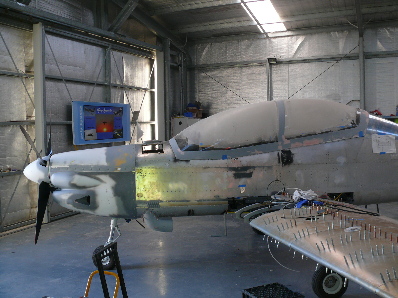


 http://www.flyinglegend.com.au/


